- 您现在的位置:买卖IC网 > Sheet目录19082 > DCE.91.131.BVM (LEMO)TOOL POSITNER FOR DPC.91.701.V
�� �
�
�?�
�?�
�Contact� resistance� with� relation� to� the� number�
�of� mating� cyles�
�(measured� according� to� IEC� 60512-2� test� 2a)�
�Average� values� measured� after� the� mating� cycles� and� the�
�salt� spray� test� according� to� IEC� 60512-6� test� 11f.�
�Insulation� resistance� between� the� contacts�
�and� contact/shell�
�(measured� according� to� IEC� 60512-2� test� 3a)�
�A?�
�(mm)�
�Contact� resistance� (m� ?� )�
�1000� 3000� 5000�
�cycles� cycles� cycles�
�A?�
�(mm)�
�Contact� resistance� (m� ?� )�
�1000� 3000� 5000�
�cycles� cycles� cycles�
�Insulating� material�
�new�
�Multipole�
�PEEK�
�>� 10� 12� ?�
�Unipole�
�PTFE�
�>� 10� 12� ?�
�0.5�
�7.5�
�8.3�
�8.7�
�3.0�
�2.0�
�2.2�
�3.1�
�after� humidity� test� 1)�
�>� 10� 10� ?�
�>� 10� 10� ?�
�0.7�
�0.9�
�1.3�
�1.6�
�5.6�
�4.1�
�2.8�
�2.6�
�5.7�
�4.2�
�2.9�
�2.7�
�6.1�
�4.8�
�3.6�
�3.5�
�4.0�
�5.0�
�6.0�
�8.0�
�1.6�
�1.4�
�1.2�
�0.8�
�2.0�
�–�
�–�
�–�
�2.8�
�–�
�–�
�–�
�2.0�
�2.9�
�3.1�
�3.3�
�12.0�
�0.7�
�–�
�–�
�Note:� 1)� 21� days� at� 95%� RH� according� to� IEC� 60068-2-3.�
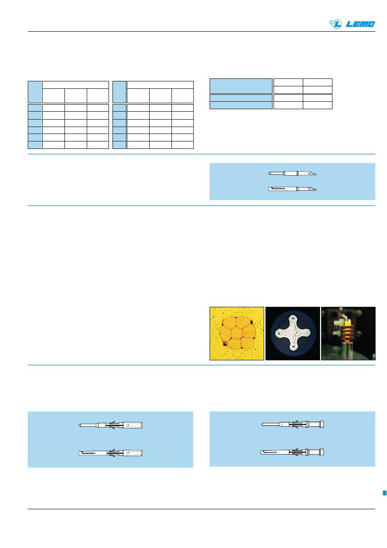
�Solder� contacts�
�The� conductor� bucket� of� these� contacts� is� machined� at� an�
����Crimp� contacts�
�The� square� form� crimp� method� is� used� (MIL-C-22520F,�
�class� I,� type� 2)� photo� 1� for� unipole� contacts.�
�For� multipole� contacts� the� standard� four� identer� crimp�
�method� is� used,� MIL-C-22520F,� class� I,� type� 1),� photo� 2.�
�The� crimp� method� requires� a� controlled� compression� to�
�obtain� a� symmetrical� deformation� of� the� conductor� strand� and�
�of� the� contact� material.� The� radial� hole� in� the� side� of� the� con-�
�tact� makes� it� possible� to� check� whether� the� conductor� is�
�correctly� positioned� within� the� contact.� A� good� crimping� is� char-�
�acterized� by� only� slightly� reduced� conductor� section� and�
�practically� no� gap.�
�Advantages� of� crimping�
�–� practical,� quick� contact� fixing� outside� the� insulator�
�–� possible� use� at� high� temperature�
�–� no� risk� of� heating� the� insulator� during� the� conductor-�
�contact� fixing�
�–� high� tensile� strength�
�Crimp� contacts� are� available� in� standard� version� (form� 1)� for�
�mounting� maximum� size� conductors.�
�For� some� dimensions,� these� crimp� contacts� can� be� pro-�
�duced� with� reduced� crimp� barrels� (form� 2)� for� mounting�
�reduced� size� conductors.�
�For� optimum� crimping� of� bronze� or� brass� contacts� they� are�
�annealed� to� relieve� internal� stress� and� reduce� material�
�1�
�2�
�3�
�hardening� during� the� crimping� process.�
�Only� the� crimping� zone� is� annealed� with� the� help� of� an�
�induction� heating� machine� designed� by� the� LEMO� Research�
�and� Development� Department� (see� photo� 3).�
�Crimp� contacts�
�The� crimp� contacts� can� be� with� two� forms:� a� standard� crimp�
�barrel� for� large� conductors� (see� fig.� 1)� or� with� a� reduced�
�crimp� barrel� for� smaller� conductors� (see� fig.� 2).�
�Fig.� 1�
�www.lemo.com�
�The� range� of� cable� dimensions� that� can� be� crimped� into�
��Fig.� 2�
�177�
�发布紧急采购,3分钟左右您将得到回复。
相关PDF资料
DCE.91.090.BVM
TOOL POSITNER FOR DPC.91.701.V
PGK-0006
FPL-GFRM ADAPTER
P51-100-S-G-P-5V-000-000
SENSOR 100PSIS 1/8 NPT 5V
P51-75-S-G-P-5V-000-000
SENSOR 75PSIS 1/8 NPT 5V
P51-50-S-G-P-5V-000-000
SENSOR 50PSIS 1/8 NPT 5V
P51-15-S-G-P-5V-000-000
SENSOR 15PSIS 1/8 NPT 5V
SBT-39-B-K11-EPC
BIG CHIP LED HB MODULE BLUE
88950302
POWER SUPP 24VDC 60W 100-240VAC
相关代理商/技术参数
DCE.91.131.FVC
功能描述:折皱器 PSTNR F. CRMP CONTCT
RoHS:否 制造商:Hirose Connector 类型: 描述/功能:Cable and Shield Crimper
DCE.91.131.FVM
功能描述:折皱器 PSTNR F. CRMP CONTCT
RoHS:否 制造商:Hirose Connector 类型: 描述/功能:Cable and Shield Crimper
DCE.91.132.BVC
功能描述:折皱器 B-SERIES MALE POSTNR 2B & 2K 1.3mm CRIMP
RoHS:否 制造商:Hirose Connector 类型: 描述/功能:Cable and Shield Crimper
DCE.91.132.BVM
功能描述:折皱器 B-SERIES FEM POSTNR 2B & 2K 1.3mm CRIMP
RoHS:否 制造商:Hirose Connector 类型: 描述/功能:Cable and Shield Crimper
DCE.91.132.CVC
功能描述:折皱器 PSTNR F. CRMP CONTCT
RoHS:否 制造商:Hirose Connector 类型: 描述/功能:Cable and Shield Crimper
DCE.91.132.CVM
功能描述:折皱器 PSTNR F. CRMP CONTCT
RoHS:否 制造商:Hirose Connector 类型: 描述/功能:Cable and Shield Crimper
DCE.91.133.BVC
功能描述:折皱器 POSITNER F CRIMP CTS
RoHS:否 制造商:Hirose Connector 类型: 描述/功能:Cable and Shield Crimper
DCE.91.133.BVCM
制造商:LEMO connectors 功能描述: